Abstraction to flange an audio signal
This is a flanger that can easily be used as an abstraction (subpatch) within any audio patch. Simply save this patch in Max's file search path with the file name "flange~.maxpat", and it can then be used as a flange~ object, as shown in the example "Try the flange~ abstraction".
The concept and the technique of flanging are explained and demonstrated in the examples, "Flanging" and "Simple flanging". The same technique is used here as in the "Flanging" example, but here we will focus on some aspects of how to encapsulate an audio process so that it can be reused in different contexts.
The norm for most MSP audio processing objects is to receive a sound signal in the leftmost inlet, and receive control parameters via other inlets, or by specific named messages in the left inlet. Initial values for some parameters of the object can usually be specified with typed-in arguments after the object's name or by initializing attributes with the @ syntax. If a parameter is stored as an attribute of the object, that attribute can usually be modified by a message in the left inlet, addressing the attribute by its name. In this patch, we try to follow all of those Max norms, so that the abstraction will behave just like a built-in MSP object.
The left inlet expects to receive the sound signal we want to flange, but it also needs to be able to receive parameter-controlling messages and attribute-modifying messages through that inlet. So all messages that come in that first inlet pass through a route object, permitting us to parse and separate the different kind of messages that might come in, using the first word in the message, also known as the "selector" of the message.
The main things we will want to control dynamically in our flanger are the rate of the flanging LFO, its depth (amplitude of variation), the wet-dry mix (the balance between processed and unprocessed sound), and the amount of feedback (of the flanger's output back into its input). So, there is an inlet for each of those parameters. The parameters can come in those inlets either as a float or as a signal, or they can be initialized as typed-in arguments in the parent patch, or the values can be provided as a rate, depth, mix, or feedback message in the left inlet. Consistent with all MSP objects, if a parameter is being controlled by a signal, then Max messages and arguments will be ignored.
One other attribute that we need to initialize is the predelay—the amount of delay that will exist in the flanger even when the depth is 0. You can think of it as the average delay, around which the LFO will fluctuate. In this patch we've chosen not to provide an inlet for the predelay, but it can be initialized by typing @predelay into the object in the parent patch, or by sending a predelay message in the left inlet. (In Max terminology, we would say that predelay is an attribute, not a message or an argument.) We use that predelay value to determine the size of the memory buffer in the tapin~ object. The size of that buffer will be set to twice the value of the predelay, allowing for maximum depth of the LFO effect.
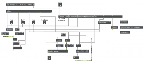
Let's take a look at the patcherargs object. Its purpose is to manage any initializing arguments or attributes that might be typed into the object in the parent patch. The user can, if s/he wants, type in initial values for rate, depth, mix, and feedback, and/or can specify the value of the predelay attribute. If nothing is typed in for those values, patcherargs provides the specified default values instead. The argument values come out the left outlet of patcherargs as a list, which we unpack with the unjoin object to send each value to its proper place (the same place as values coming in the inlets would go). Then the attribute messages (attribute name followed by attribute arguments) come out of the right outlet as separate messages, followed at the very end by the message done. Those attribute messages go through the same route object as the messages from the leftmost inlet, so the argument of the predelay attribute is parsed and sent where it's needed. (The done message is not needed in this patch, so route captures it but does nothing in response.)
Now let's look at the route object. It looks for every message selector that might come in the left inlet or from the patcherargs object, and sends the values (the arguments of those messages) to the proper places. Any incoming message that route does not expect gets sent out the rightmost outlet, and is reported in the Max Console window preceded by "flange~: does not understand ". You might be a bit confused by the use of the word signal as a message selector. Normally you would never send that word as a Max message. But all MSP objects' signal outlets send it whenever MSP is turned on, as a way to establish the network of connections between MSP objects. We want the leftmost inlet to be able to handle MSP signals as well as Max messages, so we look for the signal message with route, and (because route will send out a bang in response to a single-word message) we use the bang from route to trigger a signal message and pass it on to the tapin~ object and the patcher xfade~ object to make the connection.
Similarly, the role of the +~ objects with nothing going in the left inlet may seem hard to explain. However, the +~ objects serve the purpose of accepting either a float message or a signal in their right inlet. Since nothing is coming in the left inlet of the +~, nothing wil be added to whatever comes in the right inlet, leaving it unchanged. That way we an ensure that a signal goes into the clip~ objects (which would not accept a float in their left inlet).
The clip~ objects are there to limit the range of values that can be used in the patch. We would hope that the programmer would only send in reasonable values, but just in case not, the clip~ objects constrain whatever values come to them to stay within the specified range.
The desired range of the depth, mix, and feedback parameters is 0 to 1. It's a good idea to have some consistency of ranges, so we chose to give all of those parameters the same range. One could specify depth in milliseconds, and gain of the flanged sound in decibels, etc., but we decided that that would be a bit more confusing than having a consistent 0-to-1 range. The depth value—the amplitude of the LFO—is scaled internally to be proportional to the predelay value, so that it's expressed in milliseconds when it goes to the tapout~ object. (Note that for depth we allow values between -1 and 1, since negative and positive values have pretty much the same effect.) We limit the feedback values between -0.99 and 0.99, to avoid infinite gain increase (and negative gain is effectively the same as positive gain). For rate, a 0-to-1 range would not be very intuitive for the wide range of rates we might want, so in that case the parameter is specified in Hertz, as is the norm for an LFO.
So, to summarize, the flanger—a delay in which the delay time is conitnuously varied by an LFO—is controllable by its predelay, rate, mix, depth, and feedback parameters, which can be specified by typed-in initializing arguments in the parent patch, or by named messages coming in the left inlet, or by numbers or signals coming in the various control inlets. Once received in this patch, the messages (and signals) are properly distributed, constrained, and scaled to serve their desired purpose. The output of this object will be some mix of the unaltered input sound and the flanged sound.