Sample and hold using triggers stored in a buffer
In analog electronics, a sample-and-hold device does what its name implies, it takes a sample of the voltage coming into it at a precise instant, and holds that voltage as a constant output signal. The sampling is commonly done at regular intervals, controlled by a clock, but the it can be done in response to any triggering control signal. In MSP, the sah~ object works this way. When the signal in the right (triggering control) inlet increases beyond a specified threshold value, the signal in the left inlet is captured and sent out as a constant value, until such time as the control signal in the right inlet goes (equal to or) below the threshold and then back above it. A classic use of sample-and-hold (and of sah~) is for deriving a series of discrete signal values—discrete steps— from a continuously changing signal.
This example patch doesn’t really do anything sonic or musical, but it does demonstrate precisely how sah~ works. It also shows that there’s no inherent reason why a signal can’t be its own control signal. That is to say, the same signal can be sent into both inlets of sah~, which will have the effect of, “When the value exceeds the threshold, grab it and maintain it till it goes below the threshold and comes back up above the threshold again.” And, to demonstrate that, this patch uses triggering values stored in a buffer~, so that they can be read out at a given rate with sample accuracy.
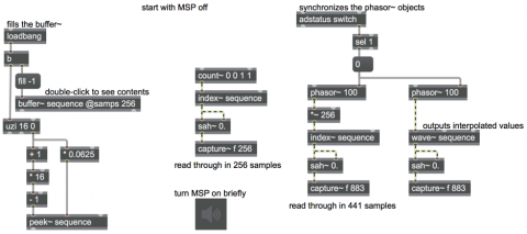
In order for this patch to work as intended, open it with MSP audio turned off.
On the left side of the patch is a buffer~ of 256 samples. When the patch is loaded, we set them all to -1, then set sixteen of the samples (indices 15, 31, 47, 63, ... 255) to unique values (0, 0.0625, 0.125, 0.1875, ... 0.9375). Now,with this you can test the other three parts of the patch by turning audio on and off.
If you step through that buffer~ at exactly the sample rate, using count~ and index~, you can see that sah~ behaves properly, using the value in its right inlet to determine whether to sample and hold the value in its left inlet. Notice that the triggering value must surpass the threshold value (must be greater than the threshold, not just equal to it), and must have been preceded by a value that was at or below the threshold.
If you want to use phasor~ to try to read through the the buffer~ at some other precise rate, you should scale the output of the phasor~ to the size of the buffer~ in samples (in this case 256) and use that as an input to index~ to look up the buffer~ value at that precise index. In the second example, the output of phasor~ will go from 0 to almost 256, so it will always be providing a lookup location from 0 to 255 to the index~ object. It's important to note that index~ does not interpolate between buffer~ values, it just truncates the index number it receives from phasor~ and uses that location in the buffer~, so it will always send out the correct value from the buffer~. We chose a rate of 100 Hz for the phasor~ so that it would read through the buffer~ in exactly 441 samples (assuming a sample rate of 44,100 samples per second). You can see that it gets through the buffer~ twice in 882 samples.
Using wave~ is not so advisable, because it takes in the input value from 0 to 1, scales that to the size of the buffer~ (or the portion of the buffer~ that you specify), and then finds the appropriate value at that location in the buffer~. But in most cases the input will result in a buffer~ location with a fractional part, such as 127.875, and wave~ will then calculate a value that is interpolated 7/8 of the way between the value at index 127 and the value at index 128. You can verify these things by turning MSP on for a moment, then double-clicking on the capture~ objects to see the samples they have captured.