Example 1: Open a sound file and play it.
This page contains links to explanations and example Max patches that are intended to give instruction on some basic concepts of interactive arts programming using Max.
The examples were written for use by students in the Interactive Arts Programming course at UCI, and are made available on the WWW for all interested Max/MSP/Jitter users and instructors. If you use the text or examples provided here, please give due credit to the author, Christopher Dobrian.
There are also some examples from the previous years' classes available on the Web: MSP examples and Jitter examples from 2004's class, and some other examples from 2005's class, examples from 2006's class and examples from 2007's class.
You can find even more MSP examples on the professor's 2007 web page for Music 147: Computer Audio and Music Programming.
And you can find still more Max/MSP/Jitter examples from the Summer 2005 COSMOS course on "Computer Music and Computer Graphics".
Please note that all the examples from these years prior to 2009 are designed for versions of Max prior to Max 5. Therefore, when opened in Max 5 they may not appear quite as they were originally designed (and as they are depicted), and they may employ some techniques that seem antiquated or obsolete due to new features introduced in Max 5. However, they should all still work correctly.
[Click on an image below to open a file of JSON code containing the actual Max patch.
Right-click on an image to download the .maxpat file directly to disk, which you can then open in Max.]
March 31, 2009
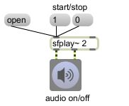
Example 1: Open a sound file and play it.
This shows an extremely bare-bones program for audio file playback.
1. Click on the speaker button to turn audio on.
2. Click on the word "open" to open a dialog box that allows you to select a soundfile. (In the dialog, select a WAVE or AIFF file and click Open.)
3. Click on "1" to start playing ("0" to stop playing).
The sfplay~ box is a normal MSP object. It performs an audio task: it plays sound files from disk and sends the audio signal out its outlets. The number 2 after sfplay~ is an 'argument', giving the object some additional information: that it should play in stereo, and thus should have two audio signal outlets. (The third outlet will send a notifying message when the soundfile is done playing, but this program doesn't use that outlet.) The speaker button (a.k.a. the ezdac~ object) is a 'user interface object'. It allows the user to interact with the program (in this case, by clicking on it with a mouse) and it performs a task (to turn audio on and off, and to play whatever audio signals it receives in its inlets as long as audio is turned on). Notice that the patch cords between the outlets of sfplay~ and ezdac~ are yellow and striped; that indicates that what is being passed between those objects is audio signal. The open, 1, and 0 objects are 'message boxes'. They are user interface objects, too. When clicked upon, they send the message they contain (in these cases, the word 'open' or the number 1 or 0) out the outlet to some other object. These messages are ones that sfplay~ understands. The plain black patch cord indicates that what is passed between these objects is a single message that happens at a specific instant in time rather than an ongoing stream of audio data. The words 'start/stop' and 'audio on/off' are called comments. They don't do anything. They're just labels to give some information.
April 2, 2009
Example 2: Trigger sound cues from the computer keyboard.
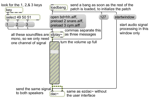
This shows how to prepare multiple sound cues for playback, and how to detect specific keystrokes in order to trigger the sound cues. It also shows how to initialize a program by triggering certain messages as soon as the patch is opened. The sound signal is sent through a multiplier to adjust the gain (volume).
This patch requires three specific sound files in order to work properly. The Max application should find these automatically in the Applications/Max5/Cycling '74/docs/tutorial-patchers/msp-tut/ folder. If not, you can download them here: they are named bd+hh.aiff, snare.aiff, and cym.aiff.
When the patch is opened, the loadbang object sends out a 'bang' message to trigger three message box objects. The first message is 'startwindow' to the dac~ object. That turns on audio for this window only, which is a good idea, because one can't know what other Max windows might be open that might make (potentially loud) sound as soon as audio is turned on; 'startwindow' activates audio objects only in the current window and any of its subwindows. The next message is 127, a MIDI-style value that sets the gain~ fader and causes it to scale whatever signal goes through it by a factor of 0.933 (just under full volume, about -0.6 dB). Then it triggers a message box that actually contains three messages, separated by commas. (The commas break up a single message into multiple messages, to be sent out one after the other as fast as possible.) Those messages open three sound files, assigning them to cue numbers 1, 2, and 3 in the sfplay~ object. They're all monophonic sound files, so there's only one channel of audio to come out, but that single signal is patched to both inlets of the dac~ object, so it goes to both speakers. When a key is typed on the computer keyboard, the key object reports the ASCII code of that key. The select object looks for the ASCII codes 49, 50, and 51--the codes for the number 1, 2, and 3 keys--and sends a 'bang' out the appropriate outlet if it detects one of those numbers. Those bangs trigger the messages '1', '2', or '3' to sfplay~ to play those cues. >
April 7, 2009
Example 3: Trigger sound cues with the mouse or from the computer keyboard.
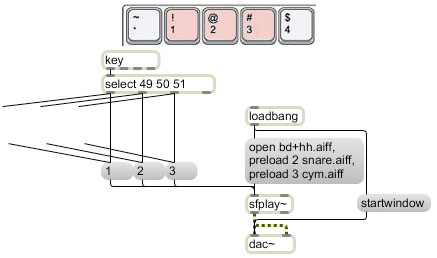
This is effectively pretty much identical to Example 2, but a) it allows the user to trigger sound cues either with the mouse or with the computer keyboard, b) it shows the user a more refined interface than just a Max patch, c) it demonstrates the use of pasted graphics and ubutton objects to make buttons on a user interface, and d) it demonstrates the use of Max 5's "presentation" mode.
The loadbang object is again used to start audio and preload the sound cues. (There's no volume control in this patch.) The three message boxes can again be triggered by the ASCII key codes coming from the computer keyboard (using the key and select objects). This time there are also three invisible buttons (ubutton objects) that the user can click on to trigger the same three messages. How does the user know to click on them if s/he can't see them? They are placed on top of a picture that has been pasted into the background of the patch with the Paste Picture command from the Edit menu. The picture should be something that invites the user to click on it (usually something buttonlike) and ideally should even give the user a good idea of what will happen if s/he does click on it (that's left as a surprise in this program). When the patch is locked and running, the ubutton objects become invisible but respond to mouse clicks just like a button object. When clicked upon, they highlight by showing an alternative color, to give the user feedback that the click has been successful. In this program we also connected the select object outlets to the ubuttons so that the appropriate keys in the graphic would appear to flash when we type on the keys.
In Max 5, you can select objects and designate them to be part of the user interface that the user will see, by choosing the Add to Presentation command from the Object menu. When the patch is put in presentation mode (by clicking on the Presentation Mode button that looks like an easel at the bottom of the Patcher window), only the objects that have been added to the presentation will be visible, and the rest of the Max objects will be hidden. Furthermore, the sizing and placement of those objects in the presentation can be set differently for presentation mode than they are in normal Max edit mode or run mode. This is very useful for creating precisely the look you want to present to the user (when it's in presentation mode) that is laid out differently from the way you want your program to be laid out when you're editing it. To cause the patch always to open in presentation mode, you can open the Patcher Inspector (from the View menu) and check the option Open in Presentation.
April 9, 2009
Example 4: All the most useful MIDI objects provided in Max.
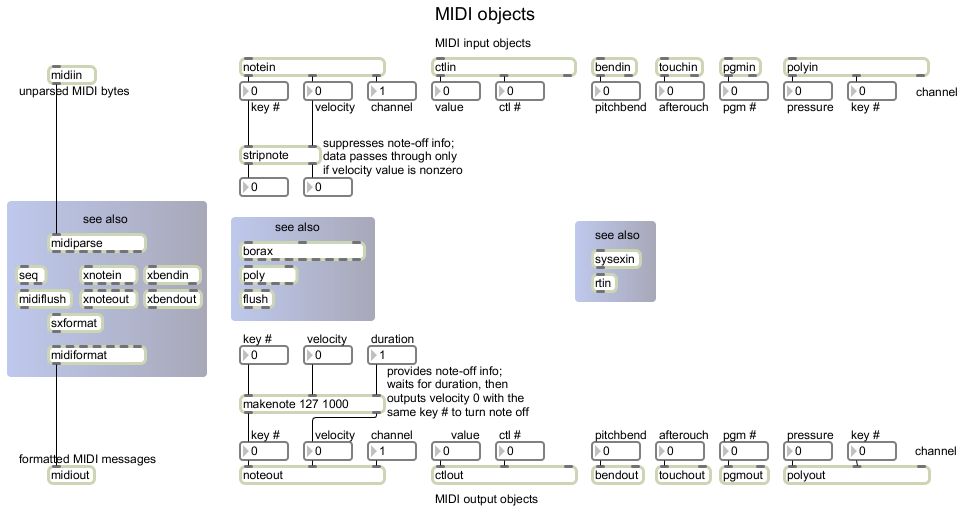
This allows you to see all the most useful MIDI objects in Max collected together in one window. If you don't know what a particular object does, option-click (or alt-click) on it to see its help file. You can send MIDI into this patch to see what kind of data it is. You can connect the midiin object to a print object if you want to see every single MIDI byte coming in.
By default, the input objects get their data from all connected devices. By default, all the output objects send their data to the first device in the list of available devices. To choose a specific MIDI device for either input or output, double-click on the object and hold the mouse down, and then choose a device from the resulting popup menu.
Example 5: Linear mapping of MIDI to amplitude.
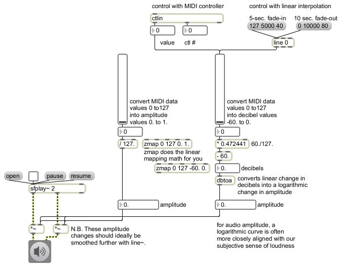
Data from a MIDI continuous controller (such as a mod wheel or a volume pedal), and/or from a Max slider object, can be used to control the amplitude of an audio signal. First the data is mapped into the appropriate range (e.g., 0 to 1), then it is used as a multiplier for the audio signal.
Note that to be truly correct, the data should go to a line~ object to interpolate sample-by-sample to the new amplitude over a very small amount of time (say, 20-50 ms or so) before going to the *~ objects. That step is omitted from this program just to simplify. You can see an example of this use of line~ in the example from April 5, 2006 called "Simple audio file player".
Linear mapping can be achieved by a multiplication to resize the range and an addition to offset the range. The zmap object (shown but not used) can do this for you. Linear interpolation over a period of time can be achieved by using the line object for Max messages (as shown in the upper right corner) or the line~ object for audio signals (not shown in this example).
To read more about linear interpolation and linear mapping, see also Dobrian's blog chapters on linear change and fading my means of interpolation.
Example 6: Drawing with MIDI notes.
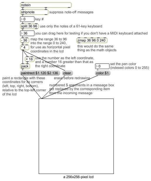
Key number data (pitch information) from a MIDI keyboard can be used to trigger and/or control events in Max, such as drawing a colored shape. First the data is mapped into the appropriate range to describe a horizontal pixel coordinate in a drawing space( e.g., pixel 0 to pixel 240). Then it is used as the left corner coordinate (and a number 16 greater than that is used as the right corner coordinate) for a 'paintrect' message to a lcd object.
Note the use of the stripnote object to suppress note-off messages (note-on message with a velocity of 0) so that a rectangle is drawn only when a key is pressed, and not when it is released. The split object is used to limit the range of notes that it will try to draw (only the most commonly-used notes, those of a standard 61-key MIDI keyboard). The valid key numbers are first used to trigger a 'clear' message to erase the previous contents of the drawing space, then to a + object to get 16 added to them, then to a pack object. The pack object is used to combine two numbers together into a single message known as a 'list' (a message that starts with a number and has other space-separated items after that). The 'list' goes to a message box that contains a properly formed 'paintrect' message with fixed top and bottom coordinates (120 and 136) and that uses the two items of the 'list' from the pack object as its left and right coordinates. The lcd object then paints a rectangle using the desired color (black by default). The 'color' message uses colors from a palette of 256 preset indexed colors, with 0=white and 255=black.
April 14, 2009
Example 7: The first sixteen harmonics of a single fundamental frequency played repeatedly at sixteen harmonically related rates.
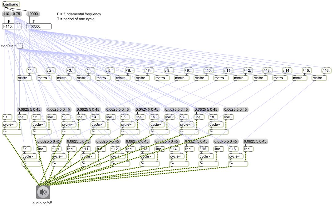
Sixteen sinusoidal oscillators are tuned to multiples 1 through 16 of a singled specified fundamental frequency, and are used to play repeated short notes (50 ms) at sixteen different harmonically-releated tempi proportional to the harmonic number of each tone. Odd harmonics are sent to the left audio output channel, and even harmonics are sent to the right audio output channel. The user can specify the fundamental frequency, and the duration of one full cycle it will take the sixteen tempi to come back into phase and repeat the cycle.
Some of the patch cords in this patch have been changed to a light color just to reduce the clutter. An ADSR envelope for each note is created by the message '0.0625 5 0. 45' to the line~ object, which sends the amplitude to 1/16 of full amplitude in 5 milliseconds and down to 0 again in 45 milliseconds, resulting in a 50-millisecond note. The amplitude of 0.0625 was chosen so that even when all sixteen notes occur simultaneously their sum will not exceed the capacity of the dac~. (In fact, since the harmonics are split up between the left and right audio output channels, the sum to either channel can never exceed 0.5.)
April 16, 2009
Example 8: Demonstration of the select object for detecting specific messages.
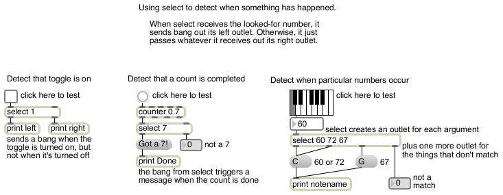
The select object asks the question "Is the thing that's coming in my left inlet equal to the thing I'm looking for?" If the answer is yes, it sends a bang out the left outlet, and if the answer is no it passes the thing it received, unchanged, out the right outlet (potentially to be used or evaluated by some other object). The bang from select (when it receives the looked-for message) can thus be used to trigger some other process. Although not shown in this example, select can look for a word as well as a number.
Notice that select is essentially doing an "is it equal to?" type of comparison, and is thus similar to the == object. However, the logical operator == works only for numbers (not for words), and it sends out a 1 or a 0 (for a yes or no answer) rather than a bang. The select object can also be used after a logical operator such as > ("is it greater than?") to detect whether the > object sent out a 1 or a 0.
If select has more than one argument, it creates an outlet for each of its typed-in arguments and the question becomes "Is the thing that's coming in my left inlet equal to one of the things I'm looking for?" If the answer is yes, it sends a bang out the appropriate outlet, and if the answer is no it passes the thing it received, unchanged, out the (extra) right outlet.
Example 9: Detecting and responding to MIDI note-ons.
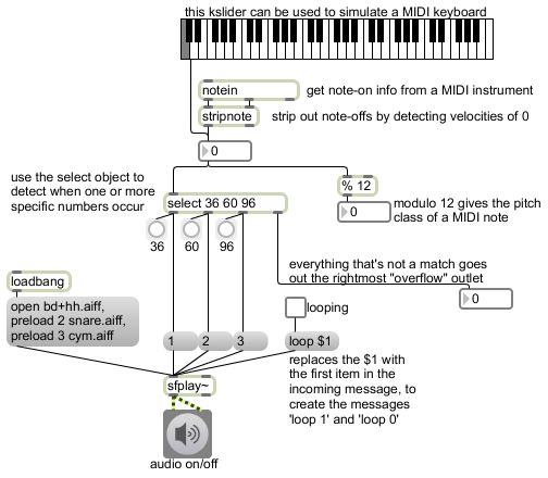
Incoming MIDI values can be used to trigger other events, processes, or media. A MIDI keyboard sends specific key number values each time any key is pressed or released. If we want our program to do something when keys are pressed, but not when they are released, the stripnote object can be used to detect note-on messages and suppress note-off messages. If the most recently received incoming velocity value in its right inlet is nonzero, then when a key number comes in its left inlet it sends out both the velocity value and the key number value. If, on the other hand, the most recently received velocity value in the right inlet is 0, stripnote sends out nothing.
The select object can be used with multiple arguments to look for multiple key numbers. (This is slightly more efficient than using multiple select objects.) In this example we look for three notes C -- the low C, the middle C, and the high C of a 61-note keyboard -- and play one of three preloaded sound cues each time those notes are detected.
This example also shows how a numbered $ argument can be used in a message box to construct a message. The $1 argument in the message box is replaced by the first item in the incoming message before the message is sent out. So in this example, the toggle object is used as an on-off switch for soundfile looping; it sends out a 1 or a 0, and the message box uses that item to construct a 'loop 1' or 'loop 0' message that sfplay~ will understand.
April 21, 2009
Example 10: Ways to specify note rate (or the speed of any events).
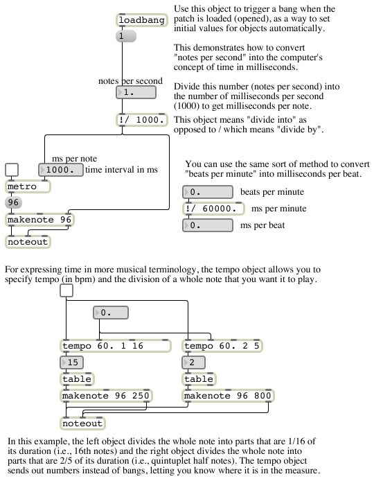
It's often useful to refer to the speed at which events occur in terms of a rate such as events-per-second or events-per-minute, rather than as an interval of time such as metro expects. This is especially true when comparing two speeds because what's usually more significant experientially is the ratio between rates or time intervals rather than the + or - difference. This patch shows simple ways to convert a rate into a period (interval) of time.
Max 5 also has a way to specify time intervals relative to a master tempo, in musical terms like quarter-note, triplet eighth note, etc. You can read about that in the blog article on tempo-relative timing and/or in the Max documentation on time value syntax.
Example 11: Random numbers to play random notes.
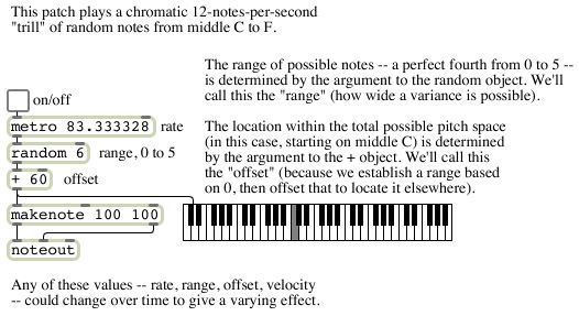
The random object pseudo-randomly chooses a number from among x possibilities, ranging from 0 to one less than the specified number x. So you can specify the range of possible numbers from which it will choose, then add some amount to the result in order to shift (offset) the range of numbers by a certain amount. In this example, we choose random numbers from 0 to 5, then add 60 to shift all the numbers into the range 60 to 65, and use those as MIDI pitch values to play a random chromatic melody.
There are several blog articles dealing with randomness, its relation to noise, limiting the range of random numbers, moving the range of random numbers over time, making probabilistic decisions, and creating probability distributions for many possibilities.
Example 12: Delaying numbers.
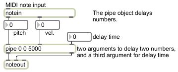
The pipe object delays number messages by a specified amount of time before passing them on. It can hold on to many numbers, each with the correct specified delay time. (The delay object, by contrast, delays a single bang message. If a new bang comes in before the old one has been passed on, the old one will be canceled.) To delay multiple separate "streams" of numbers in the same pipe object, you can type in multiple initial arguments (any combination of ints and floats), which will create additional inlets and outlets. (The final argument specifies the initial delay time.)
Example 13: Delaying numbers by a random amount of time to create irregular timing.
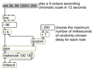
This shows a simple combination of random and pipe to create irregular timing. Each time a note number is generated, it first triggers a random delay time to be sent to the pipe object. If the delay time is small relative to the rate of events, the irregularity will be rather subtle. (Try a maximum delay of 50 or less in the example patch.) Of course you can also use it for a more extreme perturbation of a regular tempo (try a maximum delay time of 200 in the example patch, which will give the maximum perturbation without changing the order of the events), or even for a radical reordering of events (try a much larger number like 8000).
Example 14: Random transposition of notes.
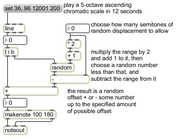
This example chooses a random pitch offset up to + or - a certain range, and applies that as a transposition of (adds it to) a series of otherwise very predictable pitch values. As a result, the melody retains some of its original directional or contour characteristics, but with randomly applied "perturbations" of the original values. You can modify the range of perturbation to create subtle or extreme perturbations.
In order to get a range of random numbers that includes both positive and negative possibilities, you double the size of the range you want (for both positive and negative values), add 1 to it (to include 0), and then offset all of the resulting numbers by your original range thus shifting half of the numbers into the negative territory.
Example 15: Transposition and inversion of incoming MIDI notes.
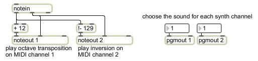
This demonstrates a couple of very simple sorts of transformations that could be imposed on incoming MIDI pitch values, before sending them on to a synthesizer. One is transposition, achieved by adding a certain number of semitones to the MIDI pitch value (and sending it out with the same velocity values as were in the incoming note messages). Another is inversion, which is achieved by choosing an axis of transposition, doubling that, and subtracting the pitch from it; so if we want to invert the incoming notes around the pitch axis 64.5 (the crack between E and F that is right at the center of the piano), we subtract the pitch from 129. (The !- object means "subtract the left input from the right input", as opposed to the - object which means "subtract the right input from the left input".)
The transposition is sent to a synthesizer on MIDI channel 1, and the inversion is sent to a synth on MIDI channel 2. You can change the timbre (i.e., the patch number) on each of those MIDI channels by sending a program change message to the pgmout objects.
Example 16: Tremolo by amplitude modulation.
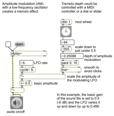
You can impose a tremolo effect (amplitude modulation) on any sound by varying its gain with a low-frequency oscillator. Whatever is being used as the basic amplitude (gain factor) of the sound can be modified by a sinusoidal signal. That is, an otherwise constant gain gets shifted upward and downward slightly by adding a small amount of low-frequency oscillation to it. The cycle~ object provides the sinusoidal signal, and its rate is initially 6 Hz (a sub-audio frequency, but about the rate of expressive tremolo that might be used by an instrumentalist). The output of that oscillator gets added to the constant value 0.5 and used to scale the amplitude of the sound file.
It doesn't make good sense for the depth of the tremolo to be so great that it turns the amplitude of the sound file completely down to 0, so we need to limit the amplitude of the modulating oscillator. Thus, we need to multiply its amplitude by some number less than 0.5. If the amplitude of the modulating oscillator is turned down to 0, there will be no modulation at all. If the amplitude of the modulator is turned up to 0.499 then the gain will vary from 0.001 to 0.999, varying up and down according to the sinusoidal shape of the modulating signal.
In order to use a physical controller such as a MIDI mod wheel (continuous controller 1) to control the depth of the tremolo, we need to map the range of MIDI data values -- 0 to 127 -- into the range 0. to 0.499 to scale the amplitude of the cycle~ object. The pack and line objects are used so that the change in the amplitude of the modulator will take place smoothly over 10 milliseconds to avoid clicks.
The rate of the LFO can be set to be extremely slow (say, 0.125 Hz) to create gradual fades up and down, or moderately slow (say, 6 Hz) for a natural tremolo rate, or even up into the audio frequency range (say, 200 Hz) for strange timbral effects. You can read more about the timbral effects of audio-rate amplitude modulation, in MSP Tutorial 9.
Example 17: Flanging a sound file by modulating the playback rate.
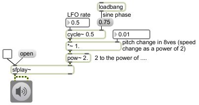
This is similar to the preceding example, in that it uses a cycle~ object as a low-frequency oscillator to modulate a sound file. In this case, the oscillator is applied to the playback rate of sfplay~. The output of the cycle~, which is from 1 to -1 by default, but which we scale down with a *~ object, is used as the exponent of base 2 for the rate. 2 to the 0th power is 1, so the sound file will play back at normal rate when the amplitude of the modulator is 0. When the amplitude of the modulating signal is 1, the rate of playback with range from 2 to the 1st power (2) down to 2 to the -1st power (0.5), thus the range of pitch change will be + and - an octave. If the amplitude of the modulator is set to 0.083333 (1/12) then the rate will vary up or down by a factor of 2 to the 1/12 power, which causes a pitch range of + or - a semitone. And so on.
The cycle~ object actually produces a cosine waveform, so its value is 1 at the moment that MSP is turned on. However, it can be provided a "phase offset" in the right inlet that will cause it to start with a different phase. The phase offset is expressed in cycles, so a phase offset of 0.75 will give a sine phase. We use this here so that the modulator starts at 0 (no modulation). However, given that the start time of the sound file is unpredictable relative to the start time of MSP being turned on in this program, it really doesn't have much practical effect in this case.
Example 18: Using the x and y mouse coordinates as pitch and amplitude controls for an oscillator.
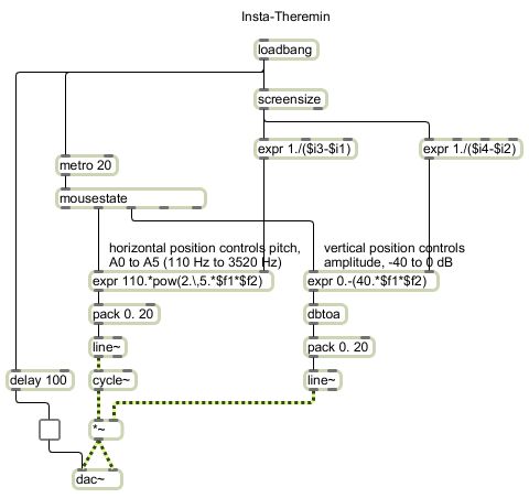
This patch, when loaded, uses the screensize object to get the pixel dimensions of the computer's main screen, then begins polling the mouse location every 20 milliseconds with mousestate and using that information to calculate a frequency and amplitude for a cycle~ object, and then turns on MSP audio. So however the user moves the mouse, it will create a variation in the oscillator's frequency and/or amplitude, creating an effect a little like a theremin.
The math might be a little confusing. The screensize object sends out the left-top-right-bottom coordinates of the screen's rectangle area as a four-item list. So subtracting item 1 from item 3 of that list will give the screen width, and subtracting item 2 from item 4 of that list will give the screen height. The inverse of those values is then stored in the right inlet of two expr objects. Since the y values increase as the mouse moves downward (measured from the top of the screen), we use the y coordinate times the inverse of the screen height as a way to find its progress from top to bottom of the screen, and multiply that by 40 (which we will use as a decibel value) and subtract that from 0. Thus as the mouse moves from top to bottom, the value coming out of expr will vary from 0 to -40 decibels. That value gets converted into a linear amplitude value by the dbtoa object, and (interpolated over 20 milliseconds by line~) that is used to scale the amplitude of the oscillator. The x coordinate is multiplied by the inverse of the screen width to calculate its progress from the left edge to the right edge of the screen, and that number times 5 is used as the exponent of base 2 times a fundmental frequency of 110 Hz, giving a frequency range of 5 octaves from 110 Hz to 3520 Hz. That is smoothed by a line~ object over 20 ms and is sent on to cycle~ to control its frequency.
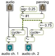
Example 19: How to set the balance (mix) of two audio signal.
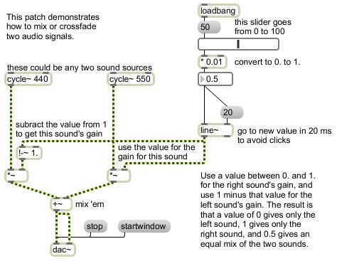
To mix two sounds together equally, you just add them together. If you know that both sounds will frequently be at or near full amplitude (peak amplitude at or near 1) then you probably want to multiply each sound by 0.5 after you add them together, to avoid clipping. However, if you want to mix two sounds unequally, with one sound having a higher gain than the other, a good way to accomplish that is to give one sound a gain between 0 and 1 and give the other sound a gain that's equal to 1 minus that amount. Thus, the sum of the two gain factors will always be 1, so the sum of the sounds will not clip. When sound A has a gain of 1, sound B will have a gain of 0, and vice versa. As one gain goes from 0 to 1, the gain of the other sound will go from 1 to 0, so you can use this method to create a smooth crossfade between two sounds.
Example 20: A useful subpatch for mixing and balancing two sounds.
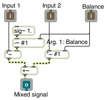
This makes the mixing technique from the preceding example into a patch that can be used as an object inside another patch. It's handy for easily mixing and/or adjusting the balance of two audio signals. Save the patch as a file with a distinct and memorable name such as "mix~.maxpat" somewhere in the Max file search path. Then you can use it as a subpatch in any other patch just by making an object named "mix~". The audio signals go into the left and middle inlets and the mix value from 0 to 1 goes into the right inlet. There are three ways to specify the balance: 1) as an argument typed into the object box, 2) as a float in the right inlet, or 3) as a signal in the right inlet. Using a signal to control mixing is the best choice if you intend to change the mix dynamically.
Whatever goes in the inlets of the mix~ object in the main patch comes out the corresponding inlet objects in the mix~ subpatch, and the mixed signal comes out the outlet. The sig~ object provides a constant signal in which every sample has the same value, in this case a constant value of 1. The argument #1 will be replaced by whatever is typed into the mix~ object box as an argument in the parent patch; if nothing is typed in, it will be 0, and if a signal is attached in the main patch then the signal value will be used. This allows the user to type in an argument to specify the initial balance value in one of the *~ objects, and the -~ object provides 1 minus that value to the other *~ object. That initial balance value can be replaced by sending in a float or a signal.
Example 21: A subpatch for transposing the pitch of MIDI notes, and ensuring that the transposed notes get turned off properly.
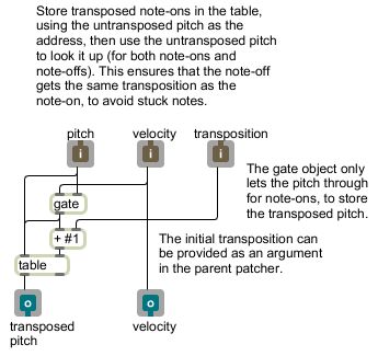
As shown in Examples 14 and 15, one can transpose a MIDI pitch value by adding a certain number of semitones to it. If the transposition is being changed while notes are being played, though, there is a possibility that the note-on message could get transposed by a different amount than its corresponding note-off, and the note would not get turned off properly. This patch solves that potential problem. Save the patch as file in the Max file search path with a distinctive name like "transpose". Pitch and velocity values go in the left and middle inlets, and a transposition goes in the right inlet; the (unchanged) velocities and the transposed pitches come out the outlets.
This patch shows the use of the table object to store values and recall them later. The number to be stored (the transposed pitch number) goes in the right inlet of the table, and the number to be used as the address to look it up goes in the left inlet of the table. Then, when a single number goes in the left inlet, it looks up the number stored at that address and sends it out.
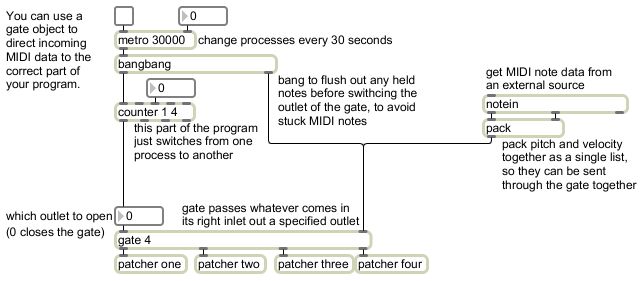
This patch also shows the use of the gate object. When a nonzero number is received in the left inlet, it opens the gate to allow whatever comes in the right inlet to pass through. When a 0 is received in the left inlet, it closes the gate and nothing can get through until the gate is opened. In this case the MIDI velocity is used to open and close the gate. When it's a note-on message, the gate is opened and the pitch goes through to get transposed and stored in the table, then it gets looked up in the table and the transposed pitch is sent out. When it's a note-off message, the velocity is 0 so the gate is closed and nothing gets through, so the previous transposition is again looked up and sent out. Once again the #1 argument is used so that the initial transposition value can be typed in as an argument in the transpose object in the main patch.
Example 22: Playing videos with the imovie object.
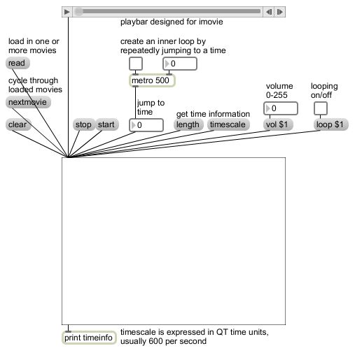
The imovie object allows you to play QuickTime movies in a patcher window. Open a movie file with the 'read' message, and use the 'start' and 'stop' messages to play and stop the movie. You can actually open more than one movie by using the read message more than once, and the imovie object will keep track of all of them. When you have more than one movie loaded in, sending the name of a loaded movie makes that movie the active one to be played. (Note that this is the same idea as the 'open' and 'preload' messages to the sfplay~ object for sound files, but for imovie you always just use the 'read' message instead; and instead of using cue numbers as for sfplay~, you use the name of the movie file to identify what you want to play.) Like sfplay~ you can turn looping on and off with the messages 'loop 1' and 'loop 0'. You can adjust the volume of the audio of the movie by sending a 'volume' message with the volume you want, on a scale from 0 to 255.
QuickTime measures time with its own distinctive unit, which is usually (but not always) 1/600 of a second (600 units per second). You can get the imovie to report the movie's number of time units per second with the 'timescale' message, and you can get it to report the length of the movie (in QuickTime time units) with the 'length' message. You can cause imovie to jump to a particular place in the movie (regardless of whether the movie is currently playing or not) by sending an integer in the inlet, representing a time (in time units). Try reading in a movie, find out its length with the 'length' message, then try jumping to different locations in the movie by sending numbers from the number box. You can get some interesting jump-cut effects by starting the movie and then turning on the metro to jump repeatedly to a particular location.
The playbar object at the top of the patch is a special object designed specifically to control the imovie object. (It doesn't have any purpose other than that.) Interestingly, there's a sort of two-way communication between the playbar and the imovie; the progress indicator of playbar will show the current location in the movie, even if you jump to a new location with a number message.
While imovie is useful and fairly easy to use, for more serious video work you will want to use jitter (jit.) objects instead. Jitter is more complicated to use than simply using imovie, but Jitter allows you to process the video image, display the movie in a separate window that can fill the whole screen, and do many other more sophisticated things with video and other sorts of visualization. We'll look at Jitter in future examples.
April 28, 2009
Example 23: Look up numbers in a table.
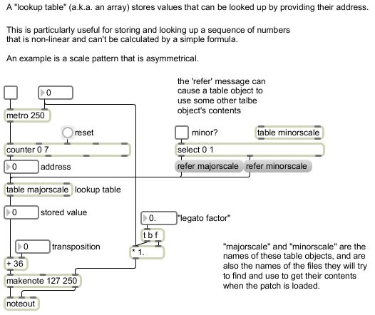
In order for this patch to work correctly, you will also need to download these two text files, and save them in the Max file search path with the names majorscale and minorscale.
An array (also known as a lookup table) is a numbered list. You look up an item in the list by specifying its number. (The numbering of items invariably starts at 0, not 1.) The index number is called the "address" and the contents of the item is called the "value" that is stored at that address. You specify the address, and the table tells you what value is stored at that address.
In Max, the table object is an array of integers. It shows you a graphic display of its contents, with the x axis being the addresses and the y axis showing the value stored at that address. When you send in an address, the stored value is sent out the outlet. The values in a table can be stored as part of the patcher (by specifying "Save Data With Patcher" in the object's inspector) or read in from a file as in this example. You can put values in a table by drawing them into the graphic window, or by creating a text file that starts with the word "table" followed by space-separated numbers.
A lookup table is particularly useful (indeed, it's indispensable) for storing and retrieving a pattern of numbers that cannot be expressed by a simple mathematical expression. Diatonic scales are examples of such a pattern, since they have an uneven pattern of whole steps and half steps that cannot easily be derived by a formula.
Example 24: Store and look up any sort of message.
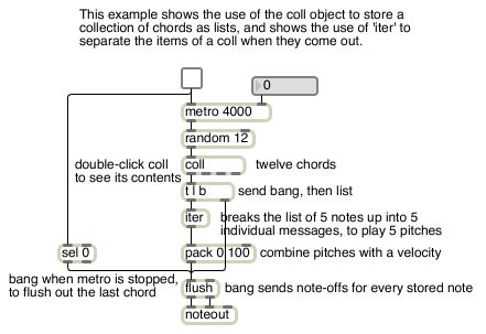
A coll object is an arbitrarily indexed collection of arbitrary messages. That is, the address can be anything, and the message can be anything. The format for each item of a coll is: [address] comma [message] semicolon. The contents of a coll can be stored as part of the patcher (by specifying "Save Data With Patcher" in the object's inspector) as in this example or read in from a file.
The messages in the coll in this example are lists of numbers that will be used as pitches of a chord. The iter object takes a list as its input and sends out the numbers in the list as separate numbers (as fast as possible). In this way, the pitches in the list that comes out of coll are all played together as a chord. The lists are twelve five-note chords (each one rooted on a different note of the chromatic scale) that are sufficiently ambiguous that almost any chord can follow any other chord, so the randomly chosen succession of chords sounds OK (if somewhat aimless).
April 30, 2009
Example 25: Disable audio processing in a subpatch.
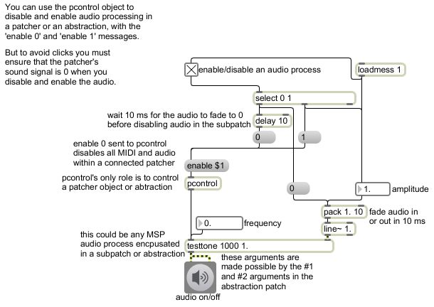
testone: Sine tone oscillator with adjustable frequency and amplitude.
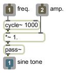
You'll need this patch to act as a subpatch in example 25.
Example 26: Disable MIDI objects in a subpatch.
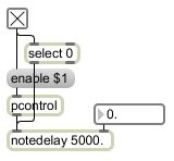
notedelay: Delay MIDI note data by a desired amount of time.
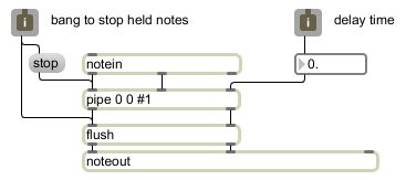
You'll need this patch to act as a subpatch in example 26.
Example 27: Switch between different MIDI processes.
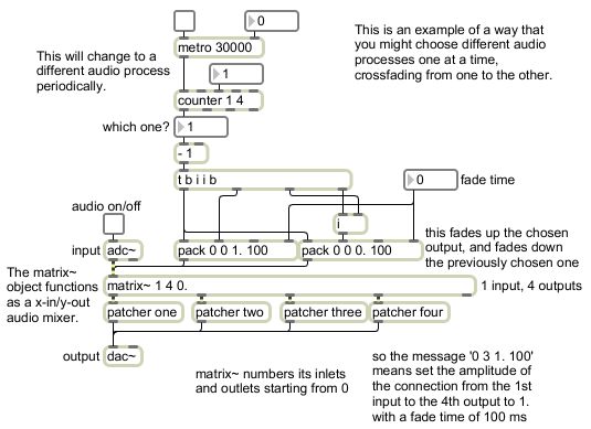
Example 28: Switch between different audio processes smoothly, by crossfading.
Example 29: Jitter attributes allow you to control features of the objects.
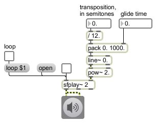
Example 30: Transpose a soundfile by a specific number of semitones, using speed change.
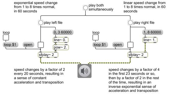
Example 31: Compare the difference between changing playback speed linearly or exponentially.
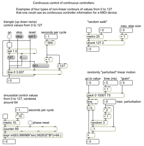
Example 32: Some ways to send non-linear contours to continuous controllers.
May 5, 2009
Example 33: Delay-based effects.
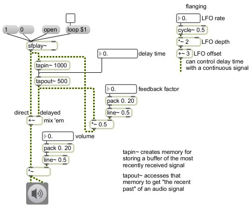
The tapin~ object continuously keeps track of the most recently received signal (its argument specifies how many milliseconds of signal to retain) and any connected tapout~ object can refer to a point in that past signal to send out a delayed copy of the original signal. When the original signal and the delayed version are mixed together, the result is the effect of a discrete echo. The output of tapout~ can be scaled down and then fed back into the input of tapin~ to create feedback -- echos of echos. (Note that since this would theoretically create an infinite loop of calculation, direct feedback like this is actually additionally delayed by Max by the duration of one signal vector.)
Very short delay times, in the range of about 30 to 80 milliseconds, are heard more as "slapback" reflections that are still recognizable as echos but that blend with the original sound. Even shorter delay times, less than about 25 milliseconds, cannot be discerned as separate events and have instead a timbral comb-filtering effect at audible frequencies.
More complex rhythmic echo effects can be achieved by tapping the delay buffer at multiple points. You can do this by attaching multiple tapout~ objects to the same tapin~, and/or by typing multiple arguments into a single tapout~ object. Sending differently delayed versions of a sound to different output channels can be used to give a "ping-pong" echo effect.
For dynamically changing delay times, the tapout~ object's delay time can be provided by a signal (from line~, for example). A continuously changing delay time creates a detuning Doppler effect. Controlling the delay time with an LFO results in a realtime vibrato effect known as "flanging". Mixing together multiple slightly-delayed versions of a sound, with the delay time of each version being controlled subtly by low-frequency random noise (as from the rand~ object) results in a realtime timbral effect known as "chorusing". For best control of comb filtering and other timbral effects with extremely short delay times (less than one signal vector) there are many filtering objects, too, such as comb~, reson~, lores~, and biquad~.
Most of the above-mentioned delay effects are described in more detail in the MSP Tutorial, chapters 27-31.
Example 34: Crossfading between two different delay times.
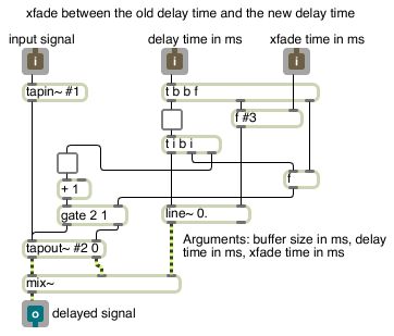
In order for the delay crossfade patch in Example 34 to work, you'll need to download the mix~ subpatch shown in Example 20 and save it in the Max file search path with the name "mix~".
If you change the delay time of a tapout~ object with a message, it risks creating a click when tapout~ leaps to a new location in the delay buffer. If you use a signal to change the delay time, there will be a pitch shift during the time that the delay time is changing due to the Doppler effect. So how do you change the delay time of a sound in real time without creating one of those (possibly undesired) effects? This program shows that you can use two differently delayed versions of the sound (two arguments typed into tapout~) and crossfade between them. The way this program is constructed, whenever a new delay time message (int or float) comes in the middle inlet, it gets directed to the tapout~ inlet that is currently faded down to 0 by the mix~ subptach, then it fades down the old delayed version and fades up the new delay time. The result is that the two delayed versions are briefly crossfaded (the crossfade could be as short as a few milliseconds, or much longer if desired) until the new delay time is at full amplitude and the old delay time is turned down to 0 amplitude. In this way the mix~ object is used to switch the balance from one delay to another, and the delay times are always sent to the inlet of tapout~ that is currently at 0 amplitude.
Example 35: A delay buffer for Jitter matrices.
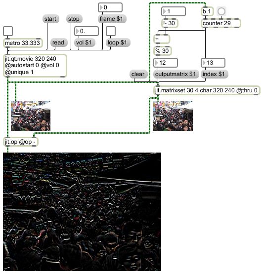
You can delay Jitter matrices by holding them in a jit.matrixset object, which is essentially an array of matrices. An 'index' message tells jit.matrixset where in the array you want to store a matrix, and subsequent 'jit-matrix' messages store the matrix in that location. An 'outputmatrix' message sends out the matrix that is stored at a particular index location. So, if you want to, you can create a continually updating ring buffer of matrices that is comparable to the tapin~/tapout~ combination for audio.
In this example, every frame that comes out of jit.qt.movie gets stored in the next available location of a 30-matrix jit.matrixset, and immediately after that it triggers an earlier-stored matrix to be sent out of jit.matrixset. The desired frame delay can be specified in the "delay" number box, offset from the current index, constrained to stay within the range 0-29, and then used in an 'outputmatix' message.
You could use this technique to create video "echo" effects (canonic repetition of a video, for example) or to composite an image with a delayed version of itself. In this example, the delayed image is subtracted from the original; the pixels that are nearly the same in the two images will thus be reduced to nearly 0.
May 14, 2009
Example 36: Linear vs. exponential change in frequency and amplitude.

Equal pitch intervals, such as semitones, are determined by equal ratios of frequency, rather than by equal differences (subtraction) of frequency. Thus, to obtain a linear pitch glissando, one must make an exponential frequency glissando. Similarly, our perception of loudness is more closely related to ratios of amplitude than to differences, so to obtain a linear-sounding fade in or out it is usually better to make an exponential change in amplitude.
In this example, on the left we use the line~ object to make a 30-second linear glissando of frequency or a 30-second linear fade-in of amplitude. In the case of the frequency glissando, you'll note that the pitch changes by an octave in different amounts of time. It goes from 50 to 100 Hz in 0.4762 seconds, from 100 Hz to 200 Hz in twice that amount of time (0.9524 seconds) and from 200 Hz to 400 Hz in twice that amount of time (1.9048 seconds). Thus, it traverses three of the six octaves of the glissando in 1/9 of the 30 seconds, and takes 8/9 of the time to traverse the next three octaves.
Likewise, the amplitude fades from -120 dB to -12 dB (i.e., from 0.000001 to 0.25), an increase by a factor of more than 250,000, in 7.5 seconds, and then fades from -12 dB to 0 dB (i.e., from 0.25 to 1.0), a factor of 4 in the remaining 22.5 seconds. These linear changes in frequency and amplitude have a non-linear perceptual/musical effect.
On the right we make linear changes in pitch, expressed in MIDI key number values, and in decibels, units which correspond to our musical perceptions, and then convert those linearly-changing signals into frequency and amplitude values, using the conversion objects mtof~ and dbtoa~. Both of those conversion formulae contain a power function that converts a linear change into an exponential one.
Example 37: Linear vs. exponential change in the rate of events.
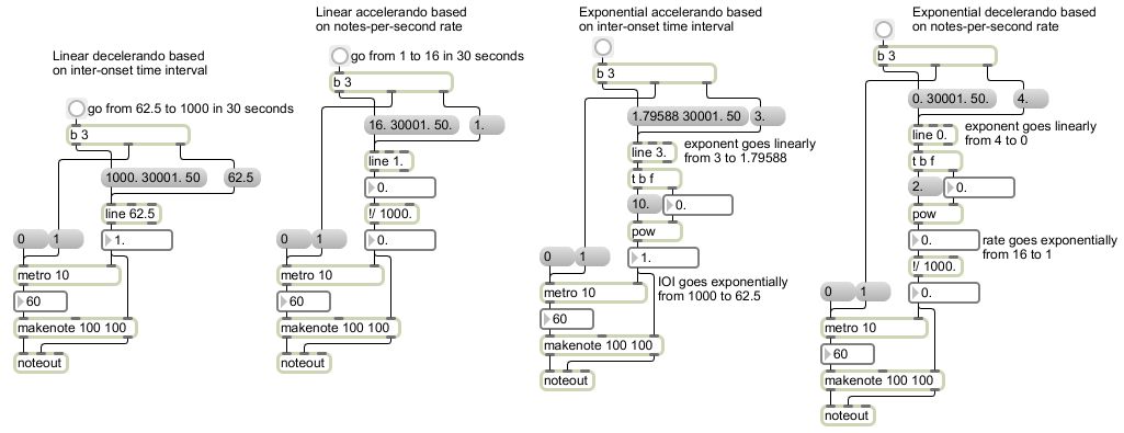
This patch provides examples that compare linear rate changes to exponential rate changes. As with pitch and loudness, our sense of change in the rate of events is based on the ratio of tempos rather than the (subtractive) difference between tempos. In these examples, the rate changes by a factor of 16, from 1 event per second to 16 events per second, or vice versa. In the two examples on the left the change is linear. In the two examples on the right, the output of line objects is used as the exponent in a pow object, thus converting the linear rate change into an exponential one. This yields, in most cases, a smoother and more linear sense of accelerando or decelerando.
May 21, 2009
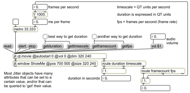
Example 38: Use attributes to control video playback in Jitter.
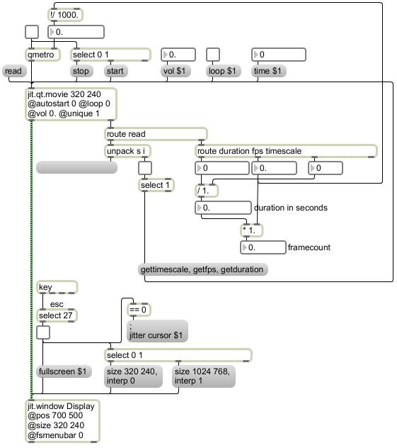
This patch shows the some of the most useful attributes of the jit.qt.movie and jit.window objects, for playing and controlling video, and demonstrates how to make use of the ability to set and get those attributes.
The arguments typed into the jit.qt.movie object set the dimensions of its internal matrix (320 by 240), set it not to start playing a video automatically when it's read in, set it not to loop a video when it reaches the end, set its audio volume to 0, and set it to output a matrix only when its contents are new and different. When you read in a movie with the 'read' message, jit.qt.movie sends a 'read' message of its own out its right outlet, consisting of the word 'read' followed by the name of the movie, followed by a 1 for a successful read or a 0 for an unsuccessful read. The "route read" object looks for messages that start with the word 'read', and sends the rest of the message out the left outlet, where it is divided by unpack. That message indicates the moment when the read has been completed, and tells whether it was successful. If it was, then the "select 1" object will trigger more attribute queries to the object itself. The attribute names preceded by 'get' cause those attributes to be reported out the right outlet (timescale, fps, and duration), where we can use them to calculate the movie's duration in seconds and its number of frames. We also use the movie's frame rate (the value of its fps attribute) to calculate the rate at which the qmetro should run. Other attributes, such as the object's volume, its loop on/off setting, and its current time in the movie (expressed in timescale units) can also be adjusted with attribute messages (such as 'vol 0.5', 'loop 1', 'time 6000', etc.).
The arguments typed in the jit.window object set the window's name ("Display"), the position of the window's top-left corner relative to the top-left corner of the screen (700 pixels over, 500 pixels down), the window's dimensions (320 x 240), and whether to show the menubar when the window is shown at fullscreen size. Other object attributes can be set with attribute messages, such as adjusting its size, turning interpolation on or off, and determining whether it should fill the full screen. We use the escape key (ASCII code 27) to toggle the fullscreen attribute on and off, because once we go to full screen the menubar will be hidden (because the fsmenubar attribute is set to 0) so the mouse will be temporarily useless.
This patch also takes advantage of the fact that Jitter itself can receive certain messages, one of which is 'cursor 0' or 'cursor 1' to hide or show the cursor. You can send messages to "max" or "dsp" or "jitter" to control some global characteristics of Max, MSP, or Jitter. Thus, when the escape key is pressed, the cursor will be toggled off, the window will be expanded and its interpolation turned on, and it will fill the full screen and hide the menubar. When the escape key is pressed again, the cursor will be toggled back on, the window size will be reduced to the way it was, and the menubar will reappear.
This patch can serve as a good starting point for any patch you want to build that plays video.
Example 39: Draw into a Jitter matrix.
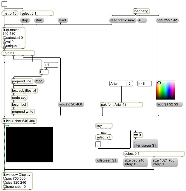
The jit.lcd object is just like the lcd object, except that instead of drawing directly onto the screen inside a Max patch, it draws into a Jitter matrix. Anything that can be drawn with lcd can be drawn on top of any other image in that matrix. So in this patch we use jit.lcd's 'write' message to write subtitles on top of a video. When the patch is opened, we use loadbang to set the foreground color of jit.lcd (the frgb attribute, which is also the pen color) and its font type and size, and to read a video into jit.qt.movie, and we read in a text file with the text object. When text gets a 'line' message it will send out a 'set' message that reports the contents of the requested line of the file. We'll use "route set" to strip off the word 'set', the tosymbol object turns the whole line into a single symbol, and the "prepend write" object turns that into a 'write' message to jit.lcd. Thus, every time we send a jit_matrix message out of jit.qt.movie, it gets transformed by the t object into a list and three bangs. The jit_matrix message is sent on to jit.lcd to fill it with a frame of video, then a bang moves the jit.lcd pen location to 20 pixels over and 460 pixels down (within the matrix), then a bang triggers the writing of a line of text in the matrix, and finally a bang triggers jit.lcd to send its contents to jit.window. The jit.lcd object provides the easiest way to write text into an image matrix, or to draw any simple 2D shape or figure into a matrix.
May 26, 2009
Example 40: Networking Max messages via UDP.
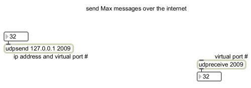
The simplest way to communicate over the internet in Max is by sending Max messages as UDP packets. The udpsend and udpreceive objects make that very easy. Tell the udpsend object what IP address to send to and what virtual port number to use, and tell the udpreceive object on the other computer the same port number. (Needless to say, for two-way communication, you just create objects to send and receive in the other direction.) In this example we use the IP address 127.0.0.1 which is a synonym for 'localhost', which loops back to the same computer, so that you can see the messages being received on the same computer.
Example 41: Networking Jitter matrices via TCP.
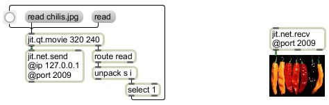
For sending large amounts of media data such as video, TCP is more reliable because the receiving computer can check that it has received packets in the proper order, and it sends back an acknowledgement messages so that the sending computer knows whether the packet was successfully received. For large packets it's best to put all the data into a Jitter matrix and send that via TCP. Of course, if you just send a 'jit_matrix' message, the receiving computer wouldn't know where to find the data, so the jit.net.send object, when it gets a 'jit_matrix' message, sends all the data contained in that matrix; when the jit.net.recv object gets the data, it puts it into a Jitter matrix of its own, then sends out the address of that matrix. Note that for these objects the IP address and port number are attributes rather than arguments.
Example 42: MSP audio over the internet via TCP.
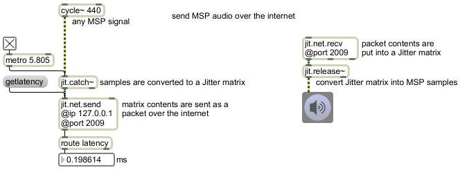
You can send audio data over the internet by first putting it into a Jitter matrix. The jit.catch~ object does that, and the jit.release~ object retrieves audio data from a Jitter matrix and sends it out as a MSP signal. By default, jit.catch~ will try to send out all the signal data it has received since the last time it sent some (i.e., since the last time it received a 'bang'). In order to avoid gltches, you should send 'bang' to jit.catch~ constantly, at a rate that will result in the optimal trade-off between latency and reliability. In this example, we send audio data every 5.085 millseconds, which is every 256 samples if the audio sample rate is 44,100 Hz. That's an acceptable audio latency in most cases, and we can see that the actual transfer latency over TCP in this case is only about 0.2 milliseconds. (Of course that's a terrific transfer time because in this example we're just sending to the same computer; actual transfer times will vary considerably.)
June 4, 2009
Example 43: Constant-intensity panning of a monophonic signal to a radial angle between stereo speakers.
This pan~ subpatch takes one signal in the left inlet, and sends it out each of two outlets. The amplitude gain for each outlet is determined by a panning value supplied in the right inlet. This value can be supplied as a typed-in argument in the main patch, as a float value, or as a control signal.
In order to change the panning without changing the over-all intensity of the sound, we need to use the square root of the panning value for each channel as the gain factor. (The reason why this is so is explained in MSP Tutorial 22, as well as in most computer audio textbooks such as Moore's Elements of Computer Music, Roads's The Computer Music Tutorial, or Dodge and Jerse's Computer Music.) Because of a trigonometric identity, the square root of values that add up to 1 can be found at corresponding locations on the first 1/4 cycle of a cosine and sine wave. So rather than do two square root calculations for every audio sample, it's computationally more efficient to "look up" the value by using the panning value as the phase offset on a 0 Hz cycle~ object. (Again, see MSP Tutorial 22 for more on this.)
This patch is useful any time you want to do simple constant-intensity panning of a single sound source to two different channels. Download it and save it with the name "pan~" and it will work as a subpatch in other patches (such as Example 44 and Example 45 below).
Example 44: Quadraphonic panning of a monophonic signal, using a left-right value and a front-back value.
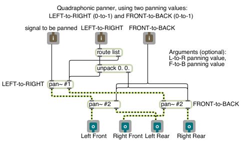
This panLRFB~ subpatch takes one signal in the left inlet, and sends it out each of four outlets. The amplitude gain for each outlet is determined by two panning values supplied in the middle and right inlets. The first value provides the left-right panning and the second value provides the front-back panning. These values can be supplied as typed-in arguments in the main patch, as float values, or as control signals. The actual gain values for the four outlets are calculated as constant-intensity panning, using the pan~ subpatch provided in Example 43 above.
The pan~ object is used here to pan the source signal left and right, and those two (left and right) signals are then each panned front and back using two more pan~ objects.
This patch is useful any time you want to do constant-intensity panning of a single sound source to four different channels that will be diffused in a rectangular speaker configuration. Download it and save it with the name "panLRFB~" and it will work as a subpatch in other patches (such as Example 45 below).
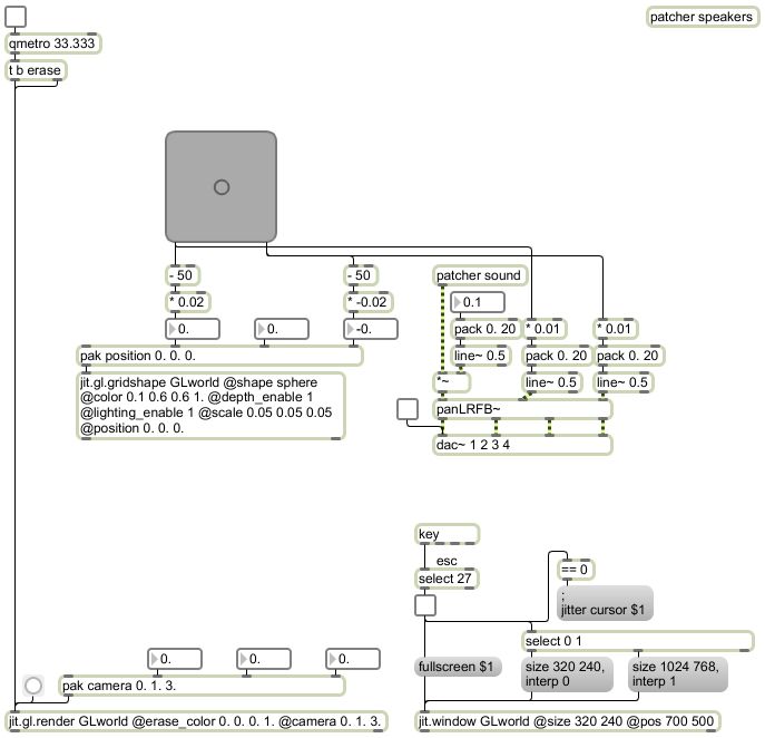
Example 45: Quadraphonic panning of a monophonic signal using XY mouse control, with the virtual sound location depicted in 3D using Open GL.
Examples are added after each class session.
This page was last modified June 5, 2009.
Christopher Dobrian
dobrian@uci.edu